Dual Warfield 8 inch series-wound motors. (225 lbs.) Series-parallel switchable high current wiring added. Motors can be configured wired in series with one another or wired in parallel with each other.
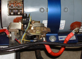

Direct drive, no transmission. Motor shafts connected with splined coupler between front and rear motors. Electric reverse added. A front motor field control contactor was added (left photo) that is normally open, closed when forward travel is selected, but opened to separate the field from the armature during reverse contactor engagement. The front motor reversing contactor setup is shown in the right photo. The upper black cube is the control relay for reverse. The green rectangle on the reverse contactor set is the mount for two small microswitches that monitor the physcal movement of the contactor's tips in case of welding.
Two piece driveline with center carrier bearing. Front and rear driveline loops.
'57 Ford nine inch axle setup out of a V8 Chevy LUV minitruck. 4:11 gears. Locked minispool. Air shocks & traction bars.
Front - Eagle 5 spoke 13 x 5.5 alloys with 4 bolt Nissan rear drive offset and 175/50/13 Nitto Exit GS radials.
Rear - Eagle 5 spoke 14 x 6 alloys with 5 bolt Ford front drive offset and DOT street legal Nitto 'Extreme Drag Radials' (22" dia.).
28 12 volt Hawker Genesis 16ahr @ 336V nominal, 378 lbs. total pack weight.

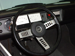
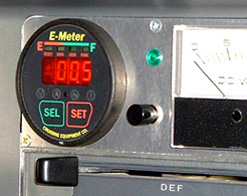
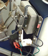
Godzilla 1200 amp programable controller. Contactor controlled series-parallel shifting added. Three high current contactors (left) configure the motors in series with each other, or in parallel with each other. The two matching 'Kilovac EV250' contactors with the positive and negative labeled cables are the parallel contactors, while the larger single 'Albright SW200' contactor on the right with the gold plated connectors is for the series mode. The series-to-parallel upshift was controlled via the small white steering wheel thumb button located near the three o'clock position on the steering wheel's right spoke (center), while the parallel release button was dash-mounted and located between the Emeter and the 12V system analog meter (right). The green pilot light just above the parallel release button lit up when parallel mode was engaged. Microswitches on the throttle pot. box interfaced with these buttons...here's how it worked. The throttle had to be a the zero position (white microswitch at bottom of the pot. box in the last photo) in order for the controller current to drop off, and in order for the steering wheel upshift button to be placed 'active' in the circuit. Pushing this button would then latch the small control relay below the pot. box which would complete the command to pull-in the parallel contactors. The black microswitch at the top of the pot. box would not allow any contactor switching at full throttle.
Car launches with motors wired in series with each other for full controller amps through both motors and highest torque, then when the throttle is momentarily let off and the button is pushed, it reconfigures the motors for parallel wiring to impress higher voltage across each motor for top speed power.
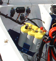

by Optima YT, no DC-DC. The addition of the series-parallel motor contactors required a rework of where the 12v system battery was placed, as shown in these before and after photos. A 12V system circuit breaker was added, and a 50 amp charge port was incuded to better facilate the external charging needed for the baby Optima.

Custom License plate replaces generic one.
2036 lbs. (est.)
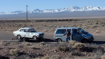

3-10-2001 Sat. ...Las Vegas Drags (1st ever)...best ET 14.312 @ 85.64 mph with battery failure 150 ft. before finish line. 1/8th ET 8.887 @ 72.40 mph, 60 ft. 2.077. Photos bellow...(left) On the road to Las Vegas with EV sidekick Marko Mongillo. (right) Returning into southern Oregon with the waning sunset as a backdrop:
7-14-2001 EV Awareness Day...White Zombie on display.